← Back to all product families
Products and systems
Incoming-material and load inspection
Systems for bales, bulk intake, sectional scanning and full-truck projects.
 04
04Application fit
Where this product family fits
Systems for bales, bulk intake, sectional scanning and full-truck projects.
Bulk-material intake
Sectional load scanning
Full-truck receiving projects
Systems and configuration options
Documented systems, components and project scope
These are representative systems and recorded system elements, not a list of independently orderable SKUs. The final supply boundary is confirmed by model, application review and order.
Each result represents only the scanned sections of the bale or load. Coverage, position, distance compensation, inaccessible zones and abnormal loads must be defined with a representative sampling plan. Grading or settlement use requires agreed acceptance and exception rules. The recorded probes, processors and software are system components, not assumed independent SKUs.
- MW-6000 bale inspection system
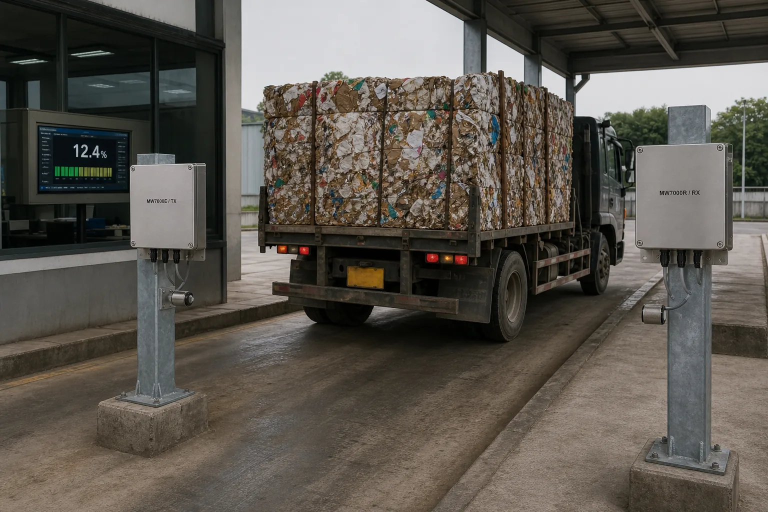
- MW-7000 full-truck system
- Ultrasonic distance probes
- Temperature compensation and dedicated software
How the family works
From measurement principle to a usable production result
Systems for bales, bulk intake, sectional scanning and full-truck projects.
Measurement principle and signal source
Incoming-inspection systems move a measurement head or the load through multiple defined positions. Distance, temperature and position data are combined with moisture response to build coverage across bales or vehicle sections.
What part of the material is represented
The result represents the scanned zones, not automatically every part of a bale or truck. Scan spacing and exception rules determine how the zones support grading or settlement.
From measurement to production action
The sensor value should travel with validity, material identity and process time. Start with trends and alarms, compare the response with operator observations, and define the exact correction or classification rule before closing the control loop.
How the result is established
Build calibration with paired samples that cover normal variation in moisture, density, temperature, product and operating state. Reserve independent samples for acceptance, document residuals and limits, and define when maintenance or process change triggers a review.
A final configuration is selected only after the measurement volume, mechanical access, influential variables, reference sampling and signal destination are understood together. The family page is the starting route; the installed system combines the appropriate sensor, controller, software, mounting and service scope for the actual process. It also defines fault behaviour, operator access and the records needed to maintain the result after handover.
Selection inputs
Confirm the application before choosing the configuration
Share your material, moisture range and process conditions to receive a focused measurement recommendation.
Contact an engineer- 1What material must be measured?
- 2Where can the sensor be installed?
- 3Surface or total moisture?
- 4How will calibration be referenced?
- 5How must the result connect to PLC, MES or settlement?