Measurement input
Receive the selected sensor, transmitter-receiver system or conditioned signal with its defined range and engineering unit.
Products and systems
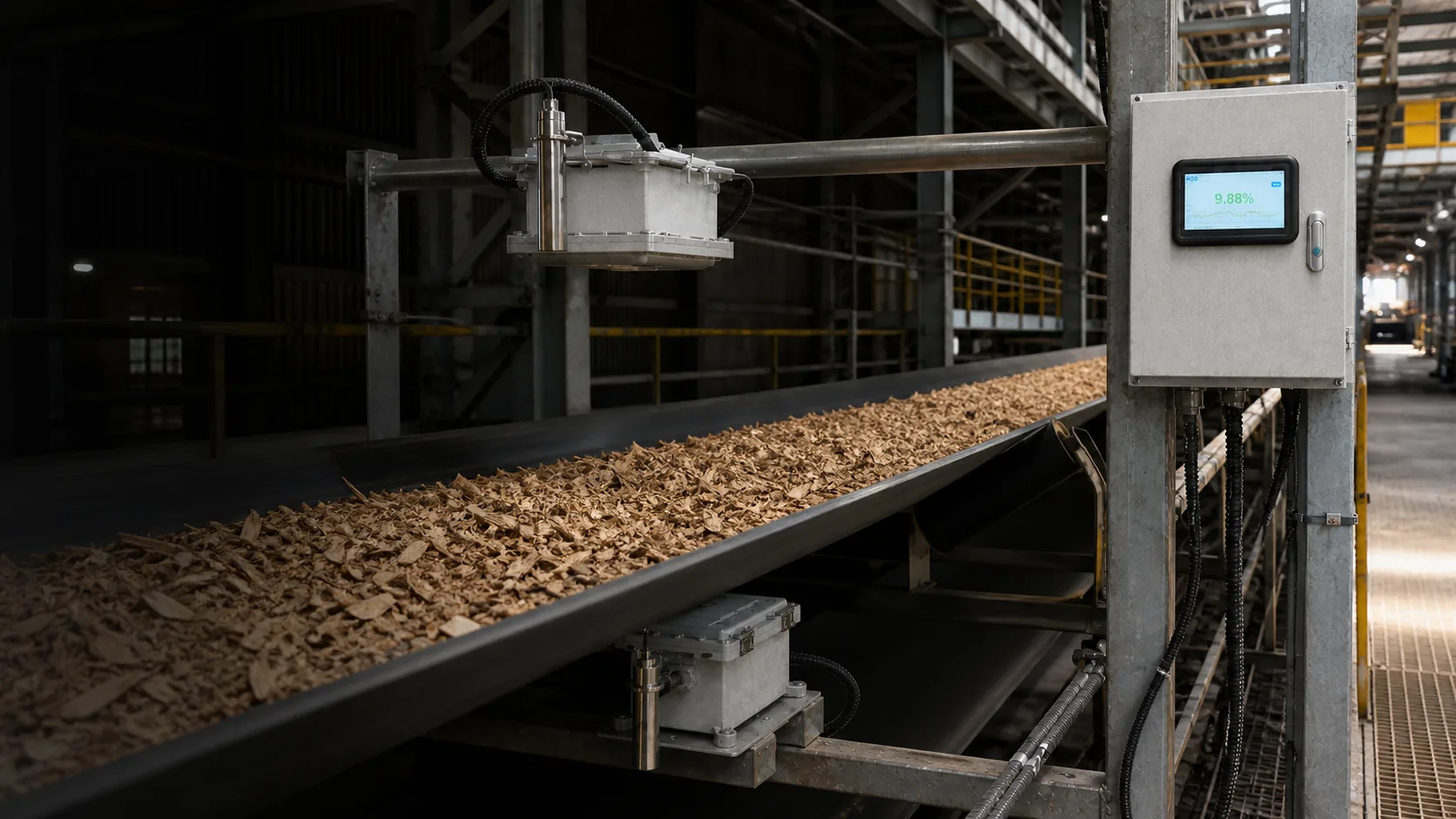
Convert sensor outputs into usable values, status, alarms and plant interfaces while preserving scale and calibration context from the operator station to PLC/SCADA.
 06
06System role
The controller is the operating bridge between sensing hardware and the plant. It must preserve the value, its validity and its configuration—not simply repeat a number on another screen.
Receive the selected sensor, transmitter-receiver system or conditioned signal with its defined range and engineering unit.
Apply the approved scaling, compensation, calibration and state logic for the connected measurement system.
Present value, trend, alarm and fault information in a form that operators can interpret and act on.
Deliver analogue or digital variables, status and records to PLC, SCADA or the control room under a documented interface.
Core functions
A control unit is selected for the connected measurement route and the decisions the plant expects to make.
Provide current value, trend, alarm acknowledgement and authorised parameter access close to the process.
Maintain engineering units, range, valid, warning and fault states without silently holding an old good value.
Support bounded manual or automatic response only after thresholds, delays and fallback behaviour are agreed.
Map registers, update rates and timestamps for PLC, SCADA or industrial-PC integration and troubleshooting.
Available equipment
Current product documentation identifies the NM-1000 display and control unit, MPC3000 and MPC6000 control units, industrial computers and touchscreen consoles. Exact I/O and protocol support is confirmed by model and project.
Signal integrity
The signal must remain interpretable through every conversion, communication step and operating state.
Verify the same range, decimal place and engineering unit at sensor, controller and PLC.
Transmit quality state explicitly so faults cannot be mistaken for stable process values.
Account for update rate, averaging and transport delay before alarms or control actions.
Record parameter, register-map and firmware changes with backup and responsible owner.
Selection inputs
Begin with what operators and automation must do with the result, then define the control hardware, signals and responsibilities required to support that action.
Contact an engineerAll blog articles
A moisture number is only useful when its engineering unit, validity, time basis and responsibility survive every step from sensor to business record.
A calibration built from convenient middle-range samples can look excellent and still fail at the operating limits that matter most.
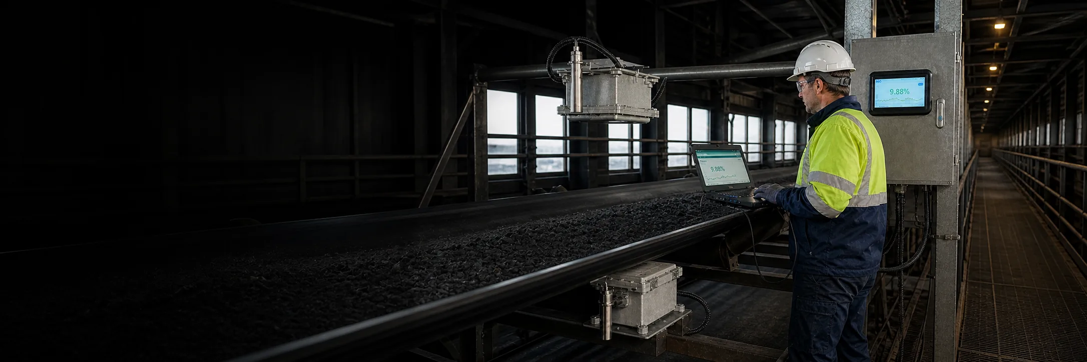
A calibration remains credible only while the measurement conditions stay inside its approved evidence range.
Complete knowledge centre
Compare measurement routes, sampling, calibration, validation and production-control guidance.