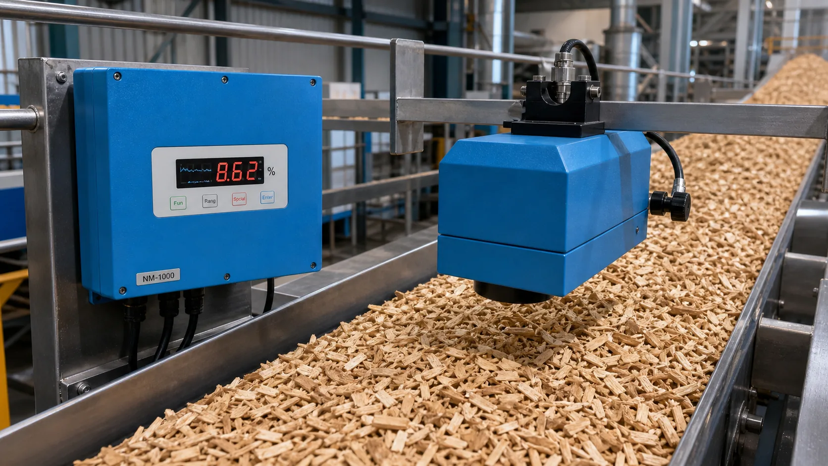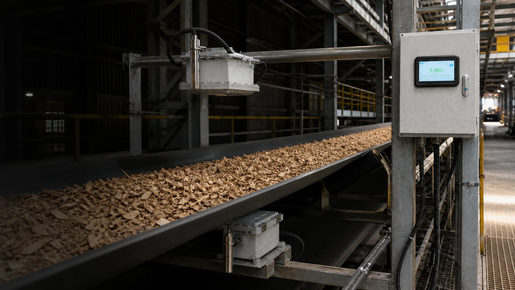
Performance depends on the material, reference method, operating range and installed configuration described in the project.
The material path is part of the signal
Microwave response changes with the amount and arrangement of material in the path. Bulk density, void fraction and bed depth can therefore change the response even when laboratory moisture is similar.
Distance and temperature need their own evidence
Optical working distance changes the observed surface. Transmission distance and material temperature can also alter the relationship, so their real ranges must appear in calibration and validation data.
Control, measure or segment the variable
Some variation can be reduced mechanically, some measured by auxiliary sensors, and some handled through material groups or models. Values outside the tested range should be flagged rather than silently extrapolated.
Build an operating-envelope matrix
Use one row per material or recipe and columns for moisture, density, depth, distance, material temperature, speed and observed maintenance state. Mark which combinations appear in calibration, independent validation or neither. This exposes unsupported corners that a one-variable range can hide.
Define the response outside the envelope
When an influential variable crosses a verified limit, the data chain should preserve the reading but mark it invalid or degraded for the intended decision. Extrapolated values must not silently drive closed-loop control, release or settlement; assign who investigates and how production proceeds meanwhile.
Before you act
Engineering checklist
- Record minimum and maximum bed depth
- Measure bulk-density variation
- Capture material and ambient temperature
- Check sensor distance and alignment
- Include extremes in independent validation