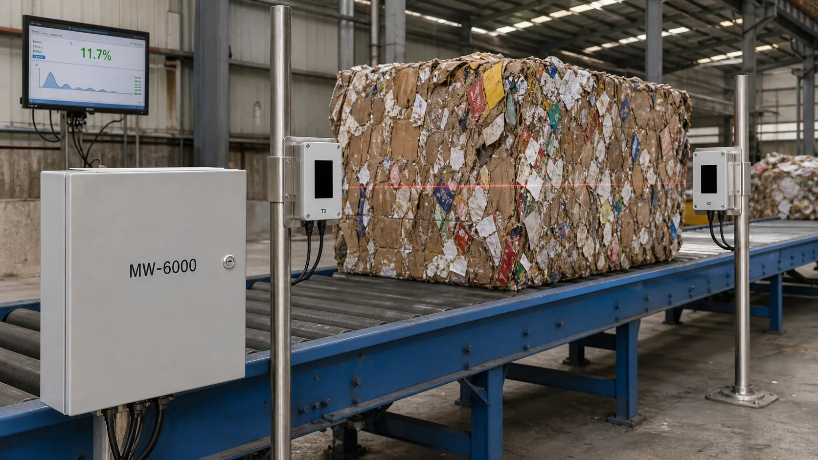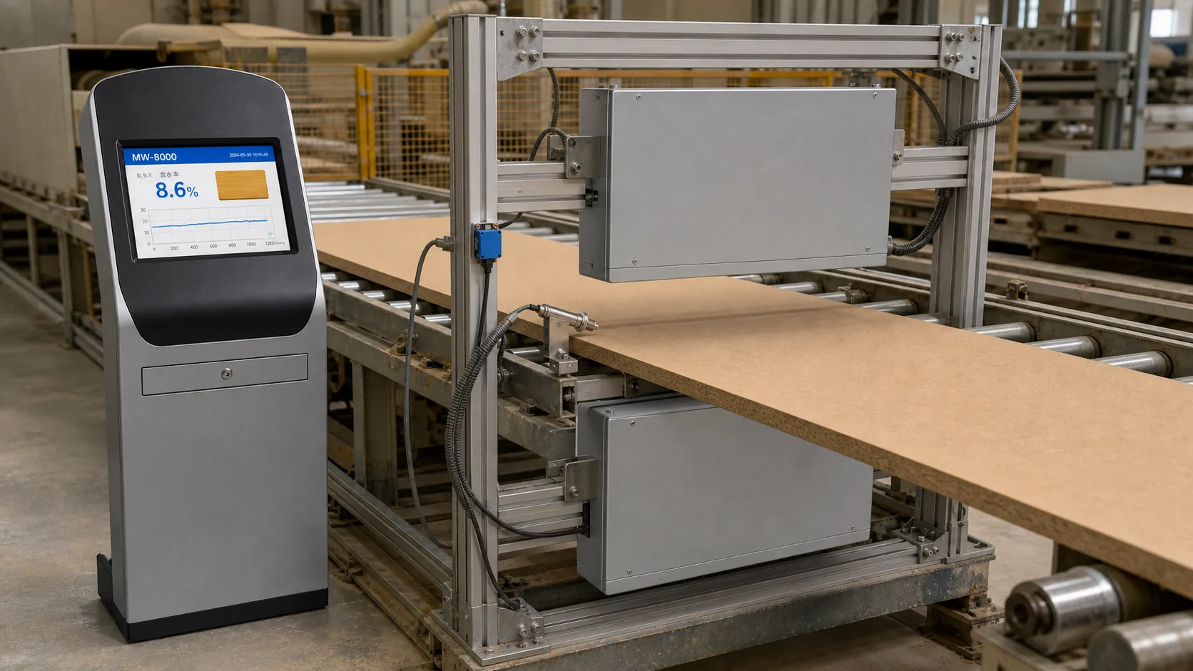
Performance depends on the material, reference method, operating range and installed configuration described in the project.
Define the product coordinates
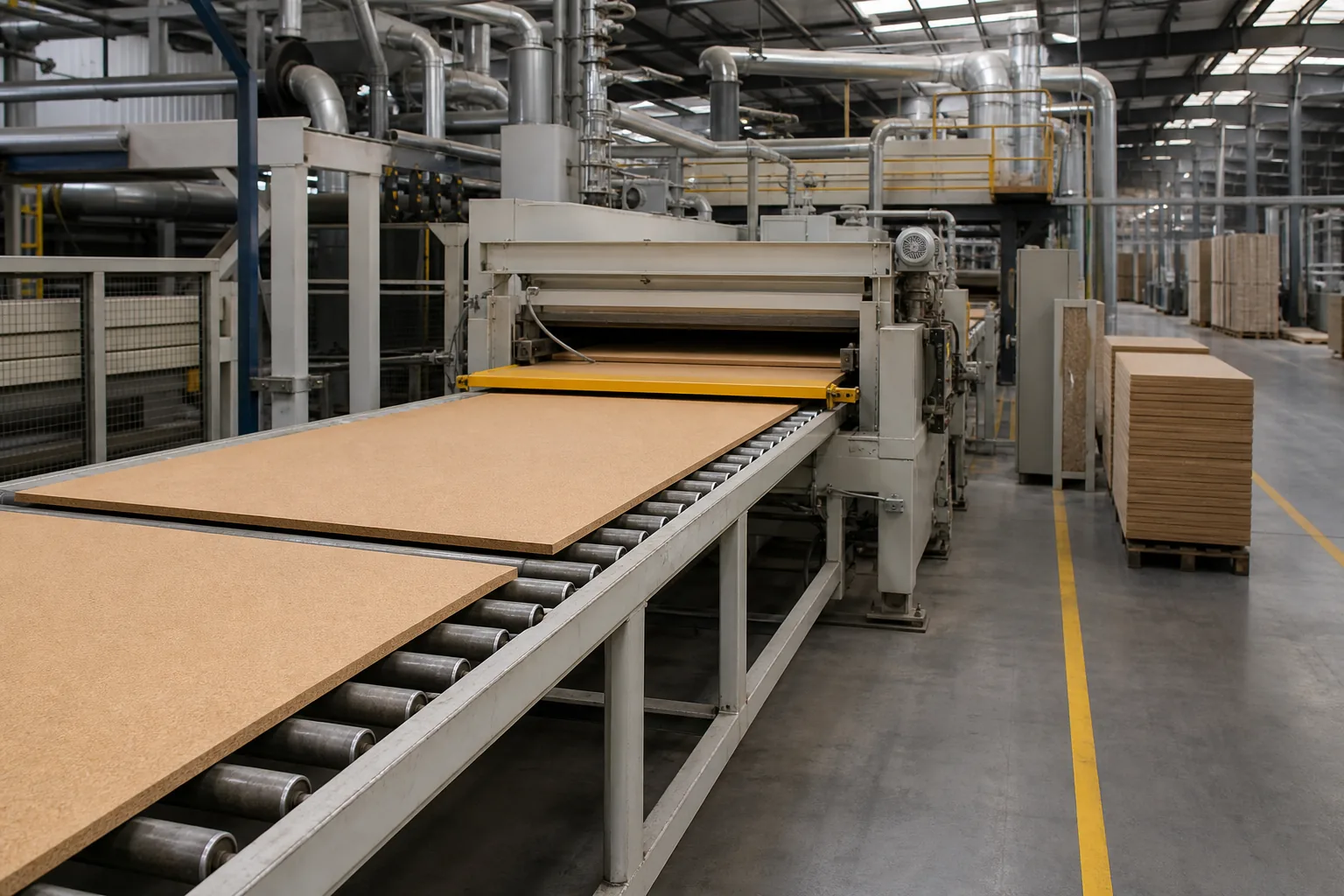
Map machine direction, cross direction, thickness and product edges. Decide whether the objective is centreline trend, width profile, section grading or defect detection.
Track changing product conditions
Thickness, density, temperature, speed, grade and gaps can alter the response. Use approved product groups and flag transitions until conditions are valid.
Align values with product identity
Compensate the delay from measurement point to cutter, stacker or reel. Store timestamp, product ID, width position, validity and summary rule.
Cut representative references
Take labelled cuts or samples from locations that correspond to measurement positions and times. Include edge and centre conditions when width variation matters.
Separate cross-profile and machine-direction decisions
Record lane positions, edge exclusions, scan pitch, line speed, board identity and synchronization. Use cross-profile values for lateral non-uniformity and time-aligned machine-direction values for process change. Do not average both dimensions into one number before checking local wet or dry zones.
Before you act
Engineering checklist
- Define width and thickness range
- Map edge and centre positions
- Track grade and product ID
- Calculate downstream delay
- Flag gaps and transitions
- Plan reference cuts